Dragonfly Inc.
Model HPD-1700
INSTALLATION AND SETUP MANUAL
|
Pressure
Transducer Triggering Device Chronic Implant Luer Lock Fittings Static Pressure
Testing
|
|||
|
(Use 'back' button to return to index) |
|||
DRAGONFLY
RESEARCH & DEVELOPMENT, INC.
P O BOX 507 RIDGELEY, WV 26753-0507 (304) 738-3609
MADE IN USA
Ó 1996-2001 DRAGONFLY, R&D, INC.
THEORY OF OPERATION
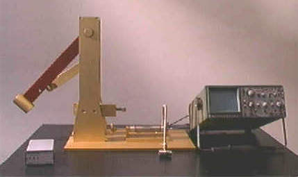
The DRAGONFLY R&D INC. MODEL # HPD-1700 FLUID PERCUSSION DEVICE is used to create reproducible closed
CNS/brain trauma injury in the laboratory rat. This device consists of a closed
hydraulic system actuated by a falling pendulum. The pressure with which the
pendulum strikes the closed hydraulic system is adjusted by changing the angle
through which the pendulum falls or by adding optional weights to the
pendulum. The system pressure is
measured directly by a precisely calibrated pressure transducer through a
charge amplifier/coupler to a digital or analog oscilloscope (digital dual-
trace with RS-232 output is ideal), or
most PC based data acquisition
systems. The timebase of the oscilloscope in combination with the mechanically
adjustable remote oscilloscope trigger allows the pressure signal to be seen at
the correct time.
The oscilloscope must
be set to trigger on a positive or rising trigger pulse. The storage function
of oscilloscope should be turned on. The time duration of the impact or
pressurization event occurs in approximately 10 ms with the flat faced striker
plate, however, it can be lengthened to 20 ms or more by gluing shock absorbing
closed cell foam on the striker plate of the piston. The time duration is read
directly on the oscilloscope using screen grid as reference.
The closed hydraulic system is attached to the animal
model using a flexible high pressure hose attached to a chronically implanted
Luer lock fitting on the rat's skull.
See “Surgical Attachment of Chronic Implant.”
SAFETY PRECAUTIONS
BEFORE PROCEEDING!
|
·
READ
ENTIRE INSTALLATION AND SETUP MANUAL BEFORE ATTEMPTING TO INSTALL OR OPERATE
THIS EQUIPMENT. ·
WEAR
EYE PROTECTION WHEN INSTALLING OR OPERATING THIS EQUIPMENT!
·
BEWARE
OF HAND PINCH HAZARD WHEN ADJUSTING
PENDULUM ANGLE. ALWAYS ADJUST PENDULUM
ANGLE USING THE BRASS PULL-PIN. DO NOT
PUT FINGERS IN AREA BENEATH PENDULUM HEIGHT ADJUSTMENT ARM!
·
CAUTION: THIS DEVICE DEVELOPS MOMENTARY HYDRAULIC
PRESSURE UP TO 200 PSI. PROTECT YOUR EYES!
·
USE
CAUTION AGAINST ELECTRICAL SHOCK WHEN USING LIQUIDS IN THE PROXIMITY OF HIGH VOLTAGE ELECTRICAL EQUIPMENT SUCH AS
OSCILLOSCOPES OR PC BASED DATA SYSTEMS.
·
KEEP
HANDS CLEAR OF PENDULUM SWING WHEN PENDULUM IS IN THE STRIKE POSITION.
· ALWAYS REMEMBER: SAFETY FIRST! |
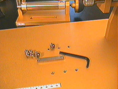
INSTALLATION
The DRAGONFLY HPD-1700 is fully assembled and tested by DRAGONFLY R&D, INC.. Note that the pendulum and the pendulum vertical support assembly has been disassembled for shipping. Remove the percussion frame assembly from its box and remove plastic covering. To install the pendulum and the pendulum vertical support assembly, remove the four screws holding the shipping spacer plate mounted to the bottom of the vertical supports. Cut and discard any nylon ties holding pendulum in place. Attach the vertical supports securely to the percussion frame baseplate using the four 1/4-20 stainless steel flat head slotted screws supplied. Note that all components are fully adjustable using the tool kit supplied. All screws should be securely tightened. Containers and shipping spacer plate may be reused in the event of return to the manufacturer for repairs or service.
The HPD-1700 must be mounted securely to an appropriate laboratory bench for effective operation. The laboratory table should be heavy and solid. If the HPD-1700 is not mounted solidly, secondary shock waves may appear in oscilloscope tracings. Drill four 1/4 inch mounting holes through the laboratory bench top using the dimensions listed in the specifications section.
Using the actual device for a drilling guide is acceptable, however use it to spot or start the hole only, then remove the device and continue drilling through the lab bench top. Attach baseplate of Percussion Device to the bench top with Neopreme TM washers between the bench top and the bottom of the Delrin TM baseplate spacers. Insert 3 of the 4 each 1/4- 20 NC baseplate screws (an assortment of lengths is included) using the Neopreme TM mounting washer assortment in conjunction with line level included in the tool kit. Use a snugging nut, a lock washer, and a locking nut beneath the bench. Do not over-tighten screws! When the baseplate is level in all directions, insert an assortment of mounting washers to fit snugly between the bench top and the base of the Percussion Device. Then insert the last mounting screw, snug nut, lock washer, and lock nut. Facing the HPD-1700 with the Piston to your right is considered “front” of the HPD-1700.
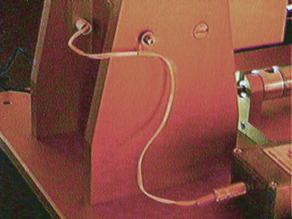
Attach the Mechanically Adjustable Magnetic Switch Assembly securely to the rear Vertical Pendulum Support using the 2 ea. flat headed 1/4-20 slotted screws supplied. Attach the Magnetic Switch wire to the rear vertical support through the plastic wire clip using the 8-32 NF plastic screw supplied. The 8-32 NF threads into the 1/4-20 Mechanical Trigger mounting screw, which has been drilled and tapped for that purpose. It is the one nearest to the pendulum end of the device.
The inclinometer/protractor supplied is used to adjust the reference angle through which the pendulum falls, and can be cross-referenced with the locking protractor as shown. Unlock the Pendulum Height Arm Locking Screw (3/4 inch wrench supplied) and adjust the angle through which the Pendulum falls as shown in the photograph, with the Pull Pin installed. When the desired angle is atained, lock the Locking Screw. Use caution not to pinch your fingers between the Pendulum Height Arm and the Vertical Pendulum Support.
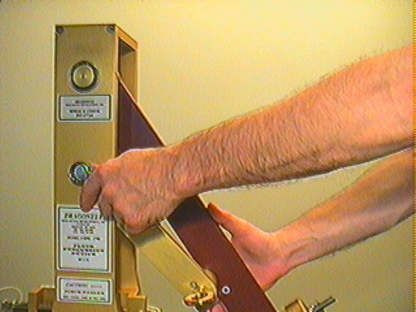
HPD-1700
Height Adjustment
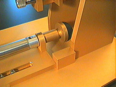
Finally,
install piston into the piston carrier plate by sliding the front diameter of
the piston into position in the Piston Carrier Plate and securing with the rear
of the piston with the knurled Stainless Steel Piston Mounting Screw supplied. Attach the Guide Key for the
Piston Carrier to the Baseplate. Secure
the piston carrier plate to the baseplate of the Fluid Percussion Device using
the 4 each Allen Head Cap Screws and thick Stainless Steel Washers supplied. A
full set of Allen TM Wrenches is supplied in the tool kit.
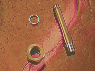
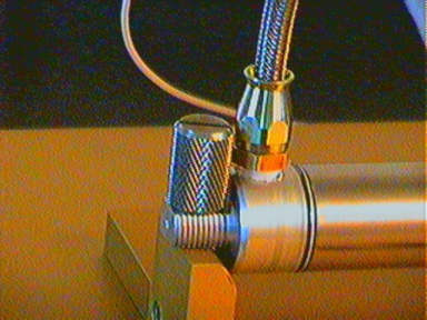
THE HIGH PRESSURE PISTON AND MANIFOLD ASSEMBLY
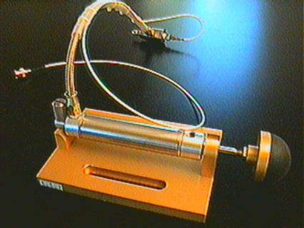
Piston/Manifold Assembly
Manifold Assembly
The high pressure piston and manifold assembly is supplied
completely assembled and tested. Periodically, though, the piston and manifold
assemblies should be disassembled and inspected for deposited contaminates.
Re-assemble using the instructions in the following section “Maintenance Of Hydraulic
System Components”. For initial setup this section can be skipped.
The piston and cylinder are used to develop hydraulic pressurization in the closed hydraulic system. Non-lubricated high pressure seals reduce introduction of contaminates into the deionized distilled water used to fill the cylinder. It is advisable to change the water often as directed in “Filling The Hydraulic Cylinder” to avoid bacterial growth or contamination in the hydraulic system, ultimately introduced to the animal model.
The cylinder and
manifold system should be removed from the
percussion platform between use and the water should be removed from the
system. The system can be dried by vigorously activating the piston in the
cylinder with the animal attachment end down. The piston and manifold assembly
can also be washed with mild detergents such as liquid dish washing detergent
in moderately warm water using the same method described. Rinse repeatedly and
thoroughly removing all detergents.
CAUTION! Harsh detergents may
damage high pressure seals!
The stainless steel high pressure manifold is a
"T" junction manifold allowing the percussion shock wave to be
hydraulically transmitted from the pressurizing cylinder to both the animal
model and the pressure transducer simultaneously. This allows direct recording
of the actual pressure ((voltage from
transducer) /(time )) in seconds developed at the animal model via the
transducer, charge amplifier/coupler and oscilloscope.
The animal can be
attached directly to the high pressure manifold if desired, or attached using
the sample plastic Pressure Monitoring Line (M/F / PVC/ 6 INCH)
supplied. Order replacements directly from
:
Dragonfly Research &
Development, Inc.
PO Box 507
Ridgeley, WV
26753-0507, USA. (304) 738-3609
(rated 800 psi, minimal
expansion under normal conditions.)
A stereotaxic table is useful in positioning the animal model. The
Manifold is easily positioned and held by hand or by an ordinary three finger
laboratory bar clamp with a weighted base. An optional Clamp with a Marble Base
and an adjustable stainless steel Arm is available from Dragonfly Research
& Development, Inc.
MAINTENANCE OF HYDRAULIC SYSTEM COMPONENTS
(Initially assembly by
Dragonfly, Inc.)
The percussion is measured directly using a precisely calibrated piezo. Assemble the pressure transducer into pressure transducer housing provided using appropriate seals included. Do not over tighten as damage may occur to transducer! Next, assemble the transducer and housing into the 1/8 NPT thread in the end of the stainless steel high pressure manifold. The pipe thread of the transducer housing should be wrapped with Teflon thread sealing tape. Wrap one thickness only in counterclockwise direction, while pulling tape to conform with the pipe thread. Do not over tighten the transducer and transducer housing into the high pressure manifold.
Wrap both ends of
the high pressure hydraulic hose with Teflon pipe tape as described above. Insert one end of the high pressure
hydraulic hose into the rear fitting of the pressurizing cylinder, and the
other end into the pipe thread fitting on the bottom of the stainless steel
high pressure manifold. Tighten the threads so that the high pressure manifold
is vertical (i.e. perpendicular plane
to table top). Do not over tighten!
After assembly, the high pressure system can be checked
for leakage using air pressure. Fill
the pressurizing cylinder with air, then block the flow of the male Luer
fitting on the high pressure manifold.
Pressurize the piston by hand while submerging the entire pressurizing
system, except for the pressure
transducer output connector,
under water. If air bubbles are
observed at any fitting, this is an indication of leakage, and that fitting
must be corrected. An alternative to
submerging the pressurizing system is to use a solution of mild dish washing liquid (high sudsing
agent) and water, or a commercial sudsing agent such as SNOOP TM to
check each fitting for leakage while pressurizing the cylinder by hand.
If the transducer output connector gets wet, dry it
with aerosol “canned air”, or a
filtered “house” air pressure hose.
Water in the Transducer Output Connector
may cause erroneous data.
FILLING THE HYDRAULIC
CYLINDER
To operate correctly,
the fluid cylinder must be “completely filled” with deionized, distilled
water insuring that no air bubbles are trapped in the cylinder, manifold, or
high pressure hoses. Trapped air bubbles will show up as momentary plateaus or
flat spots on oscilloscope tracings.
The filling
procedure is very similar in theory to that used to fill a hypodermic syringe
and remove any trapped air bubbles.
Filling is accomplished by pushing the piston in and out of the cylinder
by hand while the high pressure hose is inserted into a container of deionized,
distilled water with the stopcock in the open position (i.e. in line with the
flow). The cylinder must be physically
below the water level in the container so that any trapped air bubbles can escape. Open the stopcock on the high pressure
manifold allowing water to be pulled into and out of the piston. Operate the piston slowly by hand, back and fourth in the cylinder until no air
bubbles are observed in the exhaust stroke.. Tapping gently on cylinder,
manifold, and stopcock with wooden or plastic block may help dislodge the
bubbles. The piston is now filled and purged of air bubbles
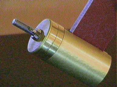
Fill the cylinder to approximately half of its stroke by slowly pushing on the piston. The gold Anodized Piston Spacer can now be used to obtain a reproducible volume of fluid in the piston. Close the stopcock before removing the manifold from the water container. The hydraulic cylinder is now ready to use. Install the cylinder back into position in the movable cylinder carrier of the HPD-1700, and remove the piston spacer.
Piston Spacer
Fluid displacement occurs momentarily during percussion into and out of the animal skull due to the compressibility of brain tissues. The minimum diameter of the closed hydraulic system is the Luer lock which is .087 inch diameter. This figure can be used to calculate the minimum cross-sectional area of the fluid path when considering the fluid dynamics of percussion.
PRESSURE TRANSDUCER
CONNECTIONS
The Quartz pressure transducer converts hydraulic
pressure in the closed hydraulic system into voltage which is displayed as the
vertical component of the oscilloscope. After mounting the pressure transducer
into the manifold as described above in
“ASSEMBLY OF HYDRAULIC SYSTEM “, simply screw the transducer cable
connector onto the transducer, then connect the BNC connector on the opposite
end of the transducer cable into the BNC input of the charge amplifier/coupler.
The transducer output is excited and AC coupled to the oscilloscope via the
amplifier/coupler with less than 100 ohms output impedance.
The maximum full scale pressure of the transducer is 200
psi. Do NOT exceed full scale pressure as permanent damage will occur.
Extremely fast transients (< 2 microsecond rise time) may show transducer
resonance superimposition. Sharp wave front pressures may excite passage
resonance which show up as secondary transient. Resonant harmonics oscillations
may also show up as secondary transients.
Large secondary transients suggest improper mounting of Fluid Percussion
Frame. Experiment using the multiple
sets of rubber shock absorbers supplied for best results in reducing secondary
transients. Entrapped air bubbles usually show up as plateaus on both the
rising and falling waveform.
.
LINEAR CONSTANT OF
TRANSDUCER SENSITIVITY = 30.76mV/psi
**** CAUTION: DO NOT EXCEED
200 PSI !!! ****
The charge amplifier/coupler requires 9 volt transistor batteries for operation.
Slide the battery cover on the bottom of the charge amplifier/coupler in the
direction indicated to gain access to battery connections. Install batteries.
Test batteries by momentarily switching on/off switch to Battery Test position.
Replace the battery cover. Replace batteries when necessary to prevent
unreliable data.
The output signal from the Pressure Transducer is
attached to the BNC input of the charge amplifier/coupler. The BNC output of the charge
amplifier/coupler is connected to the AC voltage input of one channel of the
Oscilloscope.
Connect the BNC to BNC cable from the output of the
charge amplifier/coupler into the BNC
oscilloscope input of channel one of the vertical deflection unit. Connect the second BNC to BNC cable provided
into the BNC connector of the remote oscilloscope trigger output and the opposite
end into the REMOTE TRIGGER of the oscilloscope. The remote trigger of the oscilloscope is generalized as the
EXTERNAL triggering input on the horizontal deflection unit ( i.e. the Time
Base)
OSCILLOSCOPE SETUP
The vertical deflection
unit, ( Voltage ), should be set to 1 V/div with AC coupling on channel one,
(for multi- channel oscilloscopes).
Trace alignment should be set to one major division above bottom of
display, in order to facilitate maximum viewing area for waveform. Turn
waveform storage function on. The horizontal deflection unit, ( Time Base),
initially should be set to 10 ms/div, with no additional Delay Time
factor. Triggering is set to single sweep operation on a positive
dc voltage provided by the dc voltage
amplifier of the magnetically switched remote timing unit. Set the oscilloscope to “external trigger”
using the external timing input
connector. Triggering level initially
should be set for a 50% threshold with exact value determined through trial and
error. Triggering level is set by
moving pendulum back and forth through
its sweep past the magnetic trigger switch mounted on the pendulum. Proper operation is obtained when forward
pendulum movement past the sensor
triggers the sweep of the oscilloscope trace to occur. Consult your oscilloscope manual for details on “external triggering.” If a longer timing duration is needed, the
pendulum arm can be rotated 180 degrees, however, this is rarely necessary, and
not advised.
Sample Voltage waveform to pressure calculation:
To obtain actual pressure induced in system, divide
voltage by the "constant of transducer sensitivity" of 30.76mV or
0.030.76 Volts per Psig (EXAMPLE VALUE ONLY- SEE YOUR CALIBRATION SHEET FOR ACTUAL TRANSDUCER
CONSTANT).
EXAMPLE ONLY!
2.6 Volts / 0.03076 V/Psig =
84.52 Psig induced.
Conversion of Psig to N/m squared:
1Psig = 68.95 x 1.00E -03
bar = 6894.76 N/m squared
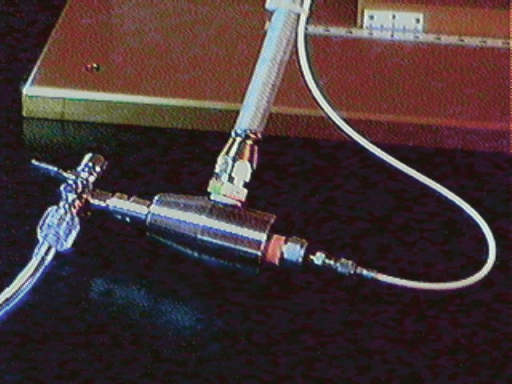
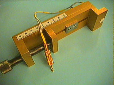
THE MECHANICALLY ADJUSTABLE REMOTE TRIGGERING DEVICE
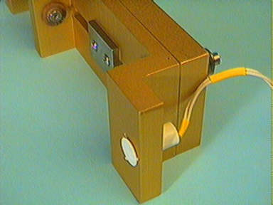
Trigger Generator
Connection to Remote Triggering Device
The Remote Triggering Device is activated when the magnet mounted in the pendulum swings past the magnetic switch mounted on the mechanically adjustable switch plate. Install a 9v. battery into the "Remote Triggering Device”. Plug the 1/8 inch male connector of the magnetic switch cable into the 1/8 inch female panel mounted connector of the Remote Triggering Device”. Plug one end of BNC cable into Remote Triggering Device” output, and the other end into the external triggering BNC input of oscilloscope. By hand, swing the pendulum back and fourth past the magnetic trigger switch. Increase the dc voltage (+) sensitivity of the oscilloscope’s time base external triggering function until a trace is observed, with oscilloscope set on single sweep mode. This indicates that the “Remote Triggering Device” is operating properly.
Trigger Timing Adjustment Assembly
The closed hydraulic system must be completely assembled and filled before trigger adjustments are performed. With the stopcock/petcock closed, adjust the mechanical trigger advance/retard mechanism into its zero position. Initially adjust and lock the pendulum height adjustment arm so that the pendulum rests at approximately 20 degrees from vertical with no additional pendulum weights. Lock the pendulum into position with the pendulum release pin.
Pressurize the piston by pulling the release pin,
allowing the pendulum to strike the piston.
The piston must be caught by hand before a second strike occurs,
otherwise repressurization will occur for each strike. Use the time base delay function and remote
trigger function of the oscilloscope in conjunction with the mechanical
adjustment of the magnetic switch to locate the event occurrence on the
oscilloscope screen, repeating the striking procedure as necessary until the
event is visible. Moving the mechanical trigger adjustment away from the piston
retards the timing of the trigger signal.
Moving the mechanical trigger adjustment toward the piston advances the
timing of the trigger signal.
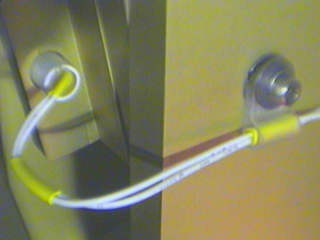
SURGICAL ATTACHMENT OF CHRONIC IMPLANT
The physical fluid connection to the anesthetized animal is achieved by chronic implantation of a Luer lock fitting or “port” mounted to the animal’s skull using dental acrylic above a hole drilled through the animal skull in the area of interest. Cranial screws (OO-90 or 000-90 thread) inserted around the fitting, imbedded in the acrylic are sometimes useful. The hole is drilled using a trephine, or a high-speed burr.
The surgical chronic implantation of the Luer
lock fitting is of vital importance to reliable pressure readings. The minimum
cross sectional diameter of the closed hydraulic system is .078 inch. Any
leakage around the chronic implant will produce a lower than actual (i.e.
false) pressure reading. A number of commercially available fittings have been
enclosed to get you started, however, no standard industry-wide fitting
currently exists. For Customized Fittings Contact:
Call or FAX for quotation:
Dragonfly R&D, Inc.
PH (304) 738-3609
FAX (304) 738-3607
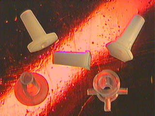
Many
investigators make their own chronically implanted male Luer fittings (headmounts) by cutting off the Luer fitting
from 5 cc plastic disposable hypodermic
syringes. We will
produce customized prototype connections and fittings to your design and
specifications. See accompanying photos of head mounted Leur ports. Both Plastic and 316 Medical Grade Stainless Steel ports are
available in a number of styles. Some models use 00-90 or 000-90 cranial screws
for positive leak-free attachment.
The correct static pressure must be set before pressurizing the animal model. The static pressure (obtained by a pendulum strike with the stopcock closed) of the closed hydraulic system is set up by trial and error, starting low and working up to the desired pressure. Percussion pressure is adjusted by changing the fall angle of pendulum, or by adding or removing pendulum weights.
Pendulum Weight Assembly
Use the inclinometer provided to check the angle of the pendulum for both strike position and pendulum angle. The inclinometer can be hand held. or attached to the trailing edge of the pendulum arm using a strong rubber band as is shown in the photograph. Remove inclinometer before striking the piston.
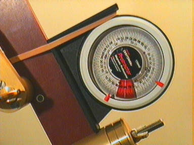
Inclinometer
The pressure is
read directly as voltage on the oscilloscope, then divided by the linear
constant of the pressure transducer (see pressure transducer calibration
certificate) to calculate the effective pressure in psig. The pendulum must
always be setup to strike the piston when it is perpendicular to the
baseplate. Adjust the piston into
striking position by adjusting the linear position of the piston carrier plate,
or by adding or subtracting water from the cylinder. Using the 3-way stopcock
and water reservoir pictured makes the latter method more convenient,
especially when multiple animal models are to be used ( See Refill Setup
Picture). Using a spacer of desired
length to return the piston to its’ same relative position between subsequent
animal models works well when using 3-way valve method with fluid reservoir
(spacer included). The piston carrier plate must always be locked securely into
position using the 1/4-20 NC Allen head cap screws and thick stainless steel
washers , or movement of the carrier plate will occur.
CAUTION: DO NOT EXCEED 200
PSI.
When the desired static pressure has been obtained, the
stopcock is opened allowing the animal model to be subjected to the shock
wave. The actual percussion pressure
(read directly as voltage on the oscilloscope) will be slightly less than the
static setting due to the displacement of tissue by the deionized, distilled
water entering the cranial cavity of the rat. The difference between static and
dynamic pressure should be minimal since only a small volume of water is
displaced.
DYNAMIC FLUID PERCUSSION
During the static pressure
test the closed hydraulic system is technically that: a closed hydraulic system. Once the stopcock/petcock is opened to
the animal model the system becomes a
semi-closed hydraulic system due to the compressibility of brain tissues.
The severity of the injury desired is obtained by
observation and experimentation, using both behavioral and pathological data to
grade injury. Conditioning animal model
by learned routines such as time-trial balance beams, Rota-Rods TM,
grip strength measurements. treadmill, inclined plane, maze or water-maze
navigation, etc. are useful in evaluating and grading the deficit incurred to
the animal model from percussion.
Pathological data such as histograms may
also be used to document results.
Record all relevant settings of HPD-1700 for each animal model experiment, including 1) the angular setting of the
pendulum (use inclinometer or angular pointer on pivot pin of pendulum), 2) the
linear setting of the piston carrier plate, 3) the linear setting of the
adjustable trigger, 4) the impact position of the front edge of the piston striker plate, 5) the amount of
pendulum weights if any, and , 6) the
composition and thickness of any closed
cell foam shock absorbers used to lengthen the time frame of the event.
Pressure and time data will be recorded on oscilloscope.
Once the desired
grade of injury is obtained, use the reference settings to recreate that same
degree of injury to as many animal models desired.